Finally, I could keep my hands clean and working on the wiring. Whilst many people would argue working on wiring is the worst part, I think it can be a bit therapeutic at times (well it was at the start). This could have also been because I was starting from scratch with a custom wiring harness, so I avoided all the old wiring gremlins.
To add a bit of a modern touch to the old motorcycle, I used a Motogadget m.unit Blue to add some additional features. Through this, I was able to add features such as remote unlocking through my phone, an alarm system that detects if someone moves your motorcycle and push button controls.
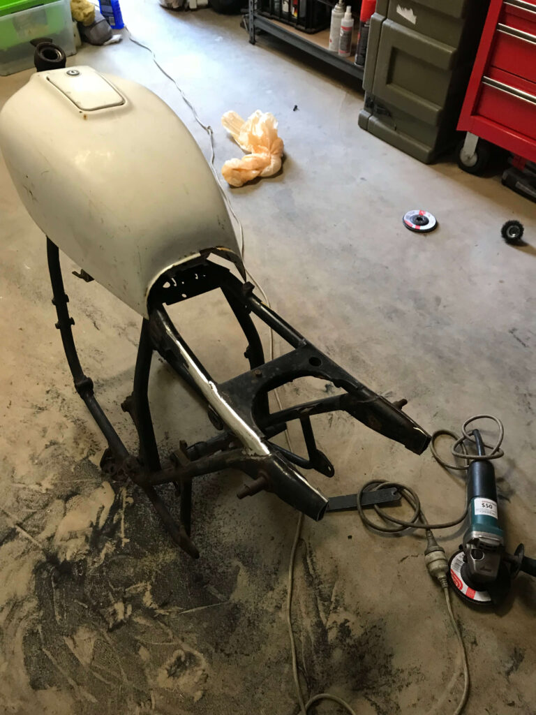
Electronics Tray
I take back what I said before, there was definitely some dirty work still left to do on the motorcycle, specifically to weld up a electronics tray. Initially, I designed the tray using cardboard and tape to get the correct shape.


Surprisingly, the cardboard model worked very well and I was able to trace out the shape of each side on some sheet metal and start bending it into shape.


After cutting each side of the tray to shape, you can see in the right image above that the tray was taking shape. It really just needed welding at this point. Now, I definitely am no welder and I have to apologies for any photos of my welding that may appear below. I will make the excuse that I was using gas-less wire which created ALOT of slag. I imagine using gas would have made it a more excuse the pun (seamless) experience. I found with gas-less that if you stopped at all, you’d have to clean the slag off and start welding again.
My recommendation is if you’re thinking of welding your own tray, definitely invest in a gas canister to save time and improve the quality of your welds.
I began by welding the tray from the inside which you can see below. Wither some greater welding knowledge in hindsight, you can observe that the weld didn’t quite adhere to the sheet metal in some sections. After some research, this is an indication that you didn’t have enough heat during the weld. It’s definitely hard to dial in correctly, where either too much heat can punch holes through the metal or it simply doesn’t adhere to the metal correctly. I also noticed there wasn’t sufficient penetration at some points, so I put down some spot welds on the outside to fill in these spots. I’m definitely more of a grinder than a welder…


At this point, you can scratch all that I did to design and weld that particular electronics tray seen in the photos above. After attempting to fit all the components (battery, m.unit, etc) into the tray, I realised I didn’t have enough space for them all. This was mainly due to the angled section I put in, which you can see in the above right photo. I also designed that particular tray quite deep as I was originally intending on using a AGM battery. However after my frustrations with the fitment issue, I took the plunge and purchased a 4-cell Lithium Anti-Gravity battery instead.
So I designed and welded another electronics tray which had the benefit of a shallower design. This meant the triangle section in the frame would be less obstructed. The previous tray had to have that angled section to allow the wheel to move freely with the suspension without hitting the tray.
I didn’t take photos of me designing and welding the new tray, largely out of the emotional trauma from doing it a second time. Though it was essentially the same process as I described above.
I could then start to arrange the electrical components on the tray to determine how they would fit. I test-fitted the components, which included the m.unit, rectifier, starter solenoid and battery. I then marked points with a sharpee for the bolts to be placed for fitment. The components were then removed and these points were drilled out.


I could then screw bolts into these holes and weld them into the tray. The excess thread sticking out of the bottom of the tray could then be cut and grinded flush to the tray.
The holes for fitment to the frame were then drilled, alongside holes for the wiring to come through.

The components could then be test fitted to the tray. Whilst they were a tight fit, there was adequate space for the wiring to be routed.

Wiring design
To design the wiring harness, I attempted to find a program online that could be used. Whilst I have used software like Altium Designer or LTspice in the past, they are more focused on circuit board design and schematics. They were not designed for wiring loom schematic design that I envisioned like you would find in workshop manuals. As such I chose my last resort and started to design the wiring diagram in MS paint.
I referred to the m.unit manual and to my CB500 workshop manual to determine how I could implement both the charging, ignition and starting systems of the CB500 with the m.unit. Luckily the m.unit makes this very easy and provides input and output pins that simplify the wiring.
Below is the diagram I ended up making for the motorcycle that has not caused me any issues.

Wiring harness construction
One large challenge I found with building a wiring harness was finding the correct wires and connectors to do the job correctly. You can’t find quality wiring in any auto shop, especially with the different colors and stripes that I wanted. After some digging around on google, I found vintageconnections.com was able to provide the parts I needed. They sell a variety of different wiring colour and gauges that also had with the correct fuel and heat resistance for motorcycle use. Furthermore, they also had quality connectors available for purchase. I was quite surprised I wasn’t able to find a business in Australia that provided this. If you know a place that does, please let me know!
I purchased all the colours I required based off my wiring diagram and off original Honda wiring colours and ensured I used the correct gauge wire for each application.
Push-button control wiring
I purchased the push button controls for the handlebar from Purpose Built Moto. To install the push button mounts, I had to drill holes into the handlebar so the wires could be routed through. To accomplish this, I test mounted the mounts in the positions I wanted them to be, and then marked with a white paint pen where I would drill. I could then drill these out and cleaned up the holes.
The push-buttons themselves did not come with any wiring, rather just metal tabs for soldering. I initially used my cheap single temperature soldering iron to do this, however all this did was melt the buttons and render them unusable. As such, I had to purchase a variable temperature soldering iron to complete the wiring. However once I did this, I realised whilst installing the buttons that the wiring gauge was way too large and interfered with the mount.. As such, I had to purchase 22AWG wiring from Rapid Cables. Finally, I was able to install the push-buttons into the mounts and route the wires through the handlebar.
Handlebar Wiring
To commence wiring, I started from the handlebars down. To start off, I cut off the length of each wire to reach from the handlebars/headlight bucket to the m.unit, plus some fat to ensure I didn’t come up short. From here, I then put bullet connectors on the end of each wire. I also put new bullet connectors on the indicators, instrument clusters, and push-button controls so they matched the ones on the wiring harness. I could them connect them all up and cable tie the harness together. For the indicators I had to solder in inline diodes so the signal from the indicators could go through the instrument cluster.


Stator Wiring
The core of the stator had frayed wires, so I had to solder in some new wiring so it could work. I then used some black silicon sealant to seal any exposed wires. I then routed these wires through the engine case as per the OEM routing. I used braided wiring sheath for this wiring and put heat shrink on each end. I also had to wire up the oil pressure switch and neutral switch, which can be seen in the image below.

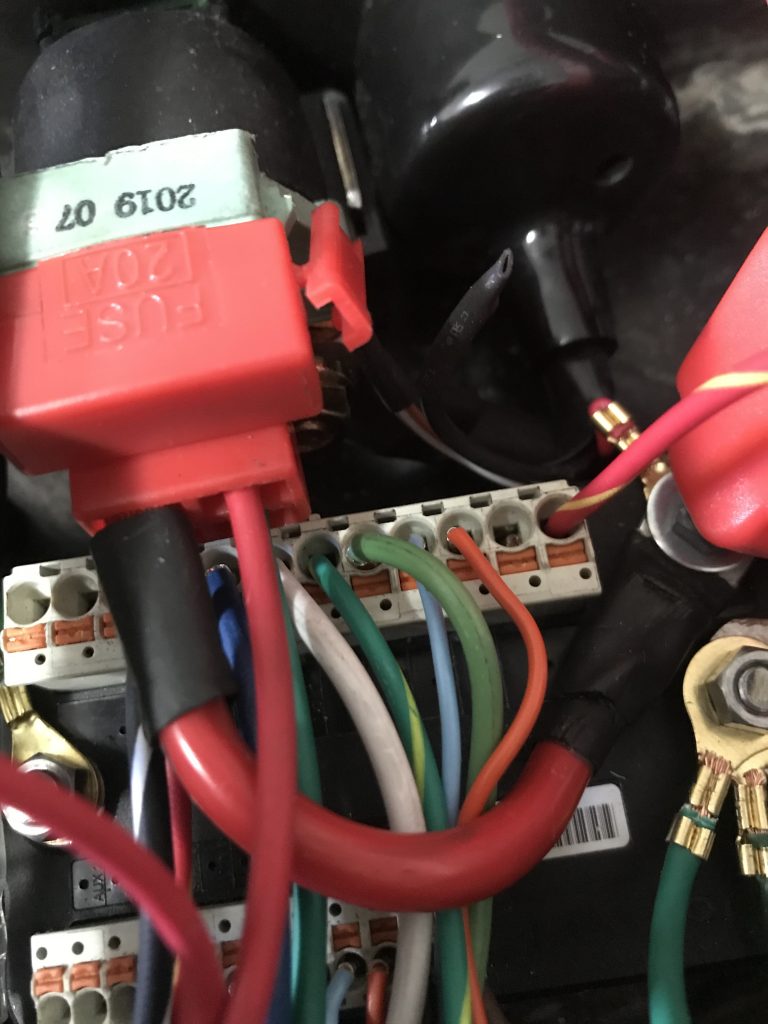
m.unit Wiring
Once the wiring was connected to the necessary connectors around the handlebar, ignition and charging system, I then routed the wiring into the electronics tray to connect them to the required components. I would cable tie the harness together and to the frame, following similar routing to the original CB500 harness. From here, I could cut the wires to the correct length and crimp on ferrules for use with the m.unit. I made sure to put rubber grommets on the electronics tray so the wiring would not get cut by the metal over time.
Wiring of the battery to the m.unit and to the starter solenoid was more difficult. Given the small space of the electronics tray, it was hard to route the larger gauge wiring from the battery to the solenoid and frame. I had to cut some small length power wires which unfortunately meant it was more difficult to move the battery once it was all connected.
For the wiring to the brake light, I had to also solder in 22AWG wiring for the LED strip alongside the LED license plate light. I had to have additional bullet connectors from the rear indicator wires to the front indicator wires so they could be wired into the m.unit.
Once all the wiring was cut and crimped to the correct length, I was able to test the m.unit. I was able to test the voltage at the coils, instrument cluster and turn the motorcycle to ‘on’ without actually starting it. Surprisingly, all components worked perfectly fine. I was also able to set up the m.unit with my phone and turn it on via Bluetooth.
With all the components of the motorcycle appearing to be working, I then removed the wiring harness. The image below shows how simple the wiring harness is with the m.unit.

With the harness removed, I could then wrap it with Tesa Cloth tape. This is the same kind of tape that is used in European cars and is easy to use and super sticky. As per the image below, it also looks good quality when used on the harness.

With the harness wrapped in the cloth tape, I then installed it back into the motorcycle for the last time. I rechecked everything was still working and could then move onto finally getting the motorcycle to start.